To share the knowledge gained in process automation in various industrial sectors we have created a 215-page guide (Download).
Physics
If submitted to compression, air molecules are forced into an ever smaller space. By decreasing the volume, the gas molecules are compressed, and the speed and number of collisions increase causing the temperature to rise.
There are two types of pressure: absolute pressure, which includes atmospheric pressure, in addition to the pressure generated, for example, by using a pump; relative pressure, which is generated by using a pump. A barometer is used to measure atmospheric pressure, while a pressure gauge is used to measure the pressure of a gas enclosed in a container.
Boyle’s Law
The state of a gas is described by three quantities: Volume, Pressure and Temperature. A particular feature of gases is their ability to expand and occupy the maximum available volume.
According to Boyle’s law, the volume occupied by a given mass of a gas, kept at a constant temperature, is inversely proportional to the pressure to which it is subjected (when the pressure is doubled, the volume is halved; if the pressure becomes one-third, the volume of the gas triples).
When a gas is heated and has the possibility of expanding its volume, pressure will not change; when a gas is heated, but cannot expand, it undergoes a pressure increase.
Gay-Lussac’s Laws
Gay-Lussac’s first law states that, at the same pressure, the volume of a gas increases in direct proportion with temperature. A gas, if submitted to temperature drops, passes from a gaseous to a liquid state. This temperature value corresponds to absolute zero. As the temperature increases, the gas expands again.
The two fundamental quantities of pneumatics are: pressure and flow rate.
Flow rate expresses the volume of a liquid that passes through the section of a duct in a unit of time. Flow rate is defined by the ratio between the volume ΔV of a liquid flowing through the duct and the time interval Δt needed to travel through it, or, if the fluid’s velocity and the duct’s section are known, by their product. The flow rate of a valve is affected by two factors: the duct’s section and the weight of the liquid column acting on the valve.
At the same pressure, flow rate depends on the difficulty or ease with which the fluid passes through a pipe or a valve, i.e. on the duct’s section (the larger the section, the more easily the fluid will pass through it). With the same section, a decrease in the pressure value will lead to a decrease in the flow rate, i.e. to a smaller quantity of fluid moving in one unit of time.
Air production
Machines that compress air are called volumetric compressors. The type of construction of the mechanical part that determines a progressive reduction of the air intake volume allows their classification either as piston or rotary compressors.
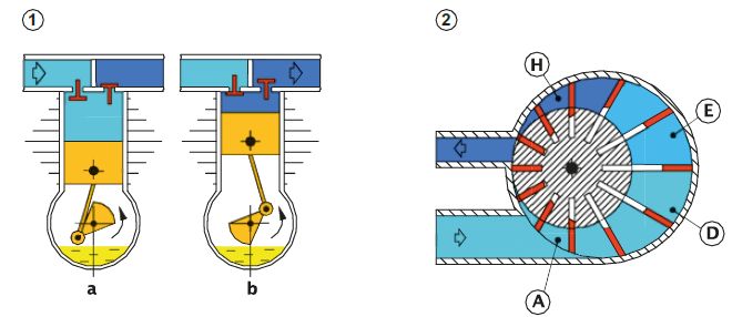
Operation of the piston compressor
The movement of some of its internal parts is similar to that of a two-stroke engine with the difference that in the compressor the “connecting rod / crank” receives its motion from another rotating machine, usually an electric motor. The final temperature can be contained by using multi-stage compressors: in the first stage, air is sucked in and compressed to an intermediate pressure; in the intermediate stage there is a cooling action; in the second stage, air is compressed to its final value.
Operation of the rotary vane compressor
Vanes, which are free to move radially, are inserted in grooves hollowed out in a cylindrical body. This body rotates inside a circular seat. The body’s axis of rotation is displaced laterally with respect to the theoretical axis of the circular seat. In this way, a space is created in which the vanes create sectors within which there is air. Unlike the piston compressor, the production of compressed air does not have reciprocating phases, but has a continuous flow. Air can be cooled by injecting oil, which must then be recovered, cooled and recycled.
Operation of the dynamic compressor
These compressors are used to compress large quantities of air. Their principle of operation is based on the movement of air by means of impellers. The kinetic energy that the air acquires is transformed into pressure energy before it leaves the compressor. Based on the shape of the impeller, compressors may be classified as radial or axial compressors.
Choice of compressor
The most important data to be defined is the amount of air required, to be calculated in Nm³/h. This is the sum of the air consumption of all connected utilities. Consumption can be continuous or intermittent (as in the case of drills, grinders, screwdrivers and the like).
A manufacturer of the latter type of items provides air consumption as a function of pressure and time. A compressor capable of supplying 50% more air than required is normally chosen and a tank is connected downstream of the compressor itself.
The air sucked in by the compressor before reaching the tank where it will be stored must pass through several intermediate items:
- Suction filter: its function is to retain solid parts of a certain size and most of the impurities found in the air being sucked;
- Chiller: when compressed the air may reach up to 200°C. By cooling the air, the chiller transforms the water vapour contained in it into water;
- Tank: it must be certified, subjected to periodic checks by the competent bodies and equipped with a safety valve (which automatically discharges the air above a certain pressure).
Along the compressed air distribution line (C/A) there are also condensate collectors, a small container with the purpose of collecting the condensate that forms along the distribution line.
Cylinders
A pneumatic cylinder is a “motor” capable of generating a force by using compressed air as a propellant. The C/A pressure is stored in the cylinder. By acting on the piston surface, such pressure generates a force that sets it in motion, provided that the air contained in the opposite chamber may be discharged. The cylinder transforms the C/A energy into mechanical energy. The force developed by a cylinder depends on pressure and on the piston’s diameter.
- Positive chamber: this is the space between the piston and the rear head. Its volume ranges from a minimum value of the end-of-stroke space to a maximum value determined by the piston stroke.
- Negative chamber: this is the space between the piston and the front head. Its volume ranges from a minimum value of the end-of-stroke space to a maximum value determined by the piston stroke. The positive and negative chambers are pneumatically independent; the chamber opposite the piston’s motion must be able to discharge.
- A Single-Acting Cylinder is constructed in such a way that the rod / piston group set returns by means of an internal spring. C/A only acts on one surface of the piston. On the other surface, there is a spring and atmospheric pressure. The presence of the return spring opposes a resistance to the piston’s motion. Force in the direction of the piston’s motion is weaker than that of a Double-Acting cylinder.
- A Double-Acting Cylinder is constructed in such a way that pressure alternately acts on both surfaces of the piston. Two directions of motion are thus obtained with the possibility of exploiting the cylinder’s force in both directions.
Kinetic Energy: this is the energy that the force applied to the cylinder acquires during its motion and must be reduced before the stroke ends to avoid an impact against the cylinder head. In order to reduce the amount of this energy, some cylinders are equipped with adjustable buffer devices that reduce speed at the end of the stroke.
There are different types of pneumatic cylinders. The most common are:
- with groove weld heads
- with heads fixed to the tube by means of tie rods
- with heads fixed to the profile using screws
- with heads integrated into the cylinder body and fixed by Seeger rings
- with screwed heads.
Magnetic cylinders enable the detection of the piston’s position. In pneumatic circuits, a cylinder is nearly always equipped with devices whose purpose is to detect the end-of-stroke position of the rod / piston group set.
The cylinder’s function is not limited to setting an object in motion. It may perform numerous activities, for example as a locking device.
When the required force is high and the piston’s diameter cannot be increased, it is possible to use cylinders in tandem. They consist of a single cylinder with double chambers and double pistons where the rod of the first piston is mechanically connected to the second piston. The resulting thrust force, slightly reduced by friction, is given by the sum of the areas of the two pistons multiplied by the pressure acting on them. Tandem cylinders can have several pistons in series and are defined as two-, three-, four-stage cylinders depending on the number of pistons.
Considering that a cylinder’s motion is rectilinear, the motion we are interested in is from rectilinear to circular motion. The set of gears capable of transforming rectilinear motion into circular motion is normally defined “rack-and-pinion” gears.
Among the various types, there are cylinders that comply with International Standards as regards their general dimensions and the distance between the fixing holes, for example:
- DIN / ISO 6432 for diameters from 8 to 25 mm
- ISO15552 replaces DIN / ISO 6431 / VDMA 24562 for diameters from 32 to 320 mm
- ISO 21287 for compact models and diameters from 20 to 100 mm.
Valves
In pneumatics, valves may be:
- Distribution valves (these have the purpose of opening, closing or diverting the C/A flow by making the cylinder take a position other than the rest position).
- Control valves (these modify the physical characteristics of the C/A). Pressure may be adjusted with “pressure-control valves”, or flow may be adjusted with “flow-control valves”. To adjust the speed of one or both strokes of the cylinder, the flow-control valve must be inserted between the distribution valve and the cylinder.
- Trap valves (they trap and/or modify the path of the C/A). The valve may trap the C/A by keeping it locked inside the chambers, or divert its path allowing a faster route towards discharge.
Classification of valves
The choice of valve depends on various parameters, including the number of positions, ways and the type of drive. Certain valve classification numbers identify the number of ways and positions. For example, 3/2 specifies a valve with 3 ways and 2 positions. The first digit always specifies the number of ways, generally 2, 3 or 5, the second specifies the number of positions, generally 2 or 3.
There may be 2, 3, 4, 5 ways. There may be 2 or 3 positions. There are valves with a higher number of positions, but they have a very limited use.
The construction principle of pneumatic valves does not depend on the number of ways or number of positions, but depends on parameters such as the sector of use, flow rate, dimensions, etc.
To change the position of a valve, it must receive a command. To provide a command, a special item called “drive unit” must be installed on the valve.
There may be different types of command: mechanical, manual, electric or pneumatic. Manual command means a command caused by the action of an operator. Mechanical command means a command caused by the movement of a mechanical item.
Drive units can be directly-controlled units (these are manual, mechanical or other controls that directly control the valve’s spool or shutter movement) or indirectly-controlled units (it is the C/A that operates the motion of the valve’s internal part). In case of pneumatically-operated valves, the drive is indirect, i.e. it is provided by an external item that opens or closes a C/A flow.
Valves may also be switched with electrical signals; however, in order to be used, an electrical signal must be transformed into a pneumatic drive. The electro-pilot, consisting of an electrical part, the solenoid and a mechanical part, the fixed core and the mobile core, performs this operation.
To stop a cylinder’s movement or maintain its position even in the absence of pneumatic power supply, either slam-shut valves or 5/3 CC valves may be used. Slam-shut valves are preferable to 5/3 CC valves because they provide greater safety.
“Logic valves” or “logic functions” are pneumatically-operated valves with reduced dimensions and flow rates. Low pressure signals are usually sufficient for the drive. They are particularly suitable for signal processing in order to create a work sequence.
Shut-off valves interrupt the C/A flow in the direction not desired. Due to the phenomenon of gas expandability, the flow direction is always towards the volume with the lowest pressure. The C/A contained in two spaces connected to each other, whatever their volume and distance, if not trapped, will distribute evenly, balancing the pressure.
The flow-control (or flow-rate) valves control the C/A flow by changing their internal section. Flow control makes it possible to adjust the travel speed of the pistons in the pneumatic cylinders. The most commonly used flow controllers are unidirectional.
To allow a system to function adequately, the pressure value must reach an adequate level for your needs and only this condition will give approval to commencing the cycle. Pressure switches are used to check whether this value remains within the figure allowed.
Circuit applications
The manual’s last two chapters show the symbols of the components and describe the way to draw and connect them together to make a diagram.
A diagram, regardless of whether it is pneumatic, electric or otherwise, is a conventional set of lines and symbols whereby it is possible to represent the functions present, their connections and the status of commands in the end-of-cycle position.
- Cylinders are represented by a rectangle, inside which the rod / piston group set is located. The group set’s position identifies whether the stem is retracted or not. The cycle of a cylinder is a succession of positive (+) and negative (-) motions of the rod / piston group set and is represented by generating a sequence diagram with letters and graphic symbols.
- Valves are represented by squares placed side by side, which define the positions that the valve may take. Arrows inside the squares specify the direction of the C/A flow.
The term elementary circuit means any simple circuits such as those for controlling a single cylinder.
- Control of a single-acting cylinder: since only one cylinder chamber has to be supplied, a 3-way, 2-position valve is used.
- Control of a double-acting cylinder: in a double-acting cylinder the C/A must be supplied for both the positive and the negative stroke. For this reason, the distribution valve must have two independent uses, i.e. a 5-way, 2-position valve.
Actuators in circuits move at different times according to a method defined by a sequence. The various phases making up the sequence occur following confirmation of the movements that have taken place. These confirmations are provided by valves with mechanical actuation devices switched directly by the actuators or by the mechanical parts connected to them. Since they may be positioned at leisure along the stroke they may be activated at the desired moment.
Principles of logic
In any pneumatic automation, in addition to defining what the sequence will be, all the information that will allow it to be carried out must be implemented. The logical rules involving a 1 or 0 state are very well suited to pneumatically-operated valves. The main logic functions that can be implemented pneumatically are: YES, NOT, AND, OR.
In some types of circuit, the brevity of even only one signal may prevent the correct operation of the cycle. Hence the need for a subsequent valve that “stores” the information even once it has ceased. A memory valve is a standard pneumatically-operated bistable 3/2 or 5/2 distribution valve. Memories in a circuit can be used to manage short-duration signals but also continuous ones defined as blocking. The timer’s function is to control a signal’s duration.